
Here are some updates leading in to the Quick & Dirty Show on March 28th.
Technology
I spent this week trying to get the phone to isadora interaction in order. This was the journey.
PHONE
Step 1: Keypad
After last week’s many attempts to get the keypad’s DTMF tone values unsuccessfully, I met with both Tom Igoe and Eric Rosenthal. After testing the keypad with Eric, it turns out that the DTMF tones were not working. Mystery solved. But that meant I needed to hack the insides of the keypad by adding a separate system underneath the original keypad, within the phone’s original console – in order to keep the vintage aesthetic.
I began by testing out various keypads to see which would fit within the console. I searched Digikey, Adafruit, sparkfun and various sites for a keypad about the same size as the original keypad, within a reasonable budget that could arrive in two days. I did not find a perfect fit, but I did find several options that I ordered and tested out.
I first opened the keypad to reveal its analog core.
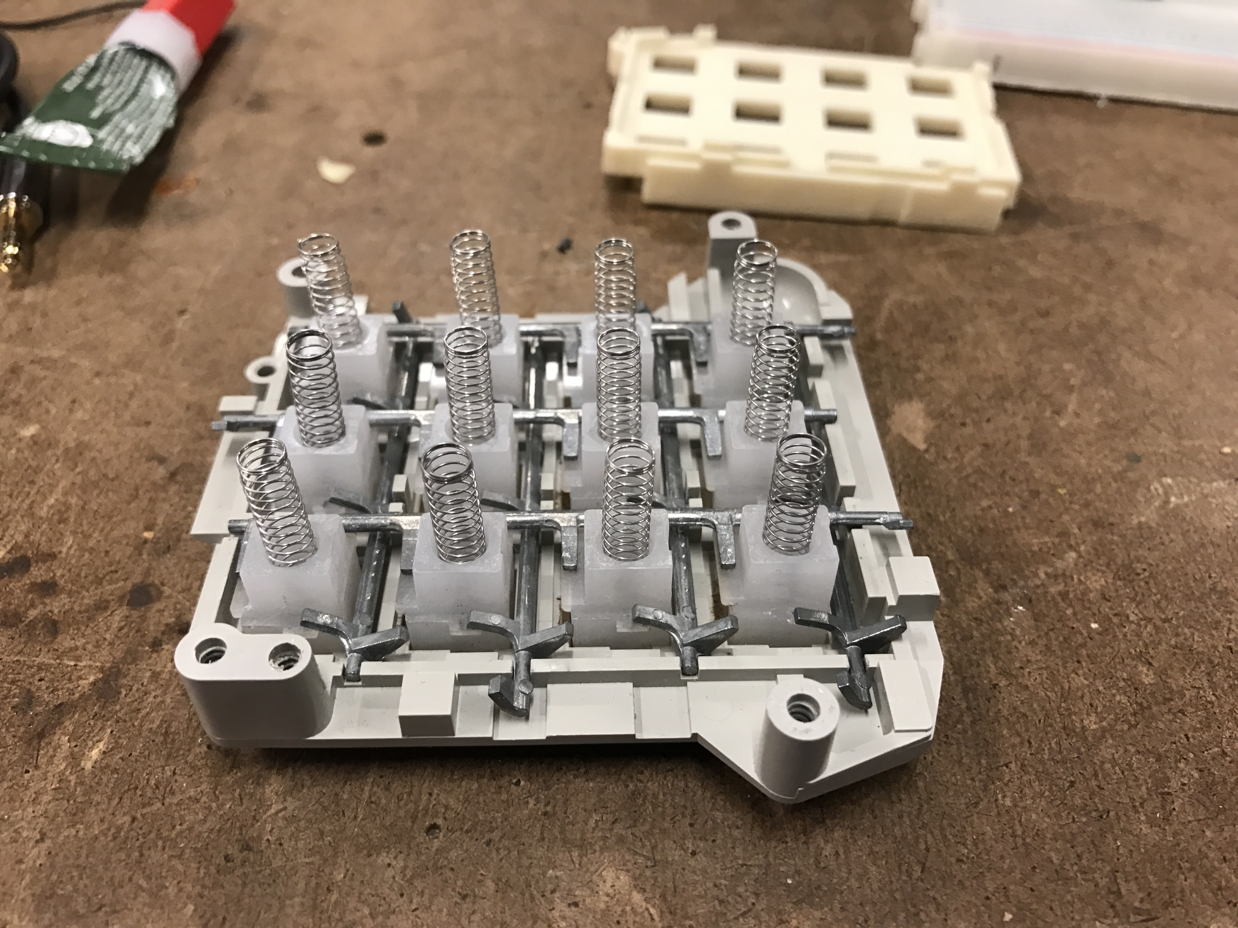

I tested out a flat keypad.

Even after cutting the sides of the keypad down, it did not fit inside the original framework to sit close enough to the buttons, and at that distance between the buttons and the keypad, the pressure of the springs was not strong enough to push down the flat base keypad
So I moved back to the keypad I tested out last week. Since it is much smaller than the phone’s keypad, I needed to set it up so that somehow all of the buttons would touch, for even just a fraction of a corner. They did not need to line up perfect.y.

I tested the values with the arduino, and once I found that sweet spot where the new keypad matched with the original keypad buttons, I hot glued them together on the sides to lock the keypads into place.

I needed to stack the arduino beneath the keypads to ultimately place within the framework of the phone. In order to stack efficiently, I made a mini shield for the wires to go from the keypad to the arduino, that could rest neatly between the layers.

Step 2: Headset
As tested with Eric, the headset was in working order in a scenario where it receives 5v or more.
I took the two wires coming from the cord from the back of the phone and soldered them to an audio jack cable. The sound came through but it was extremely muffled, low and illegible.
Speaking with Chino Kim, who has worked with phone hackery in the past, I was advised to try out using a transformer. This website offers an exquisite explanation of this type of connection and how to go about one possibility to make a vintage headset work. The circuit came out to look like this:


The result with the transistor was that the noise was enhanced and louder…better but still super muffled and very difficult to understand.
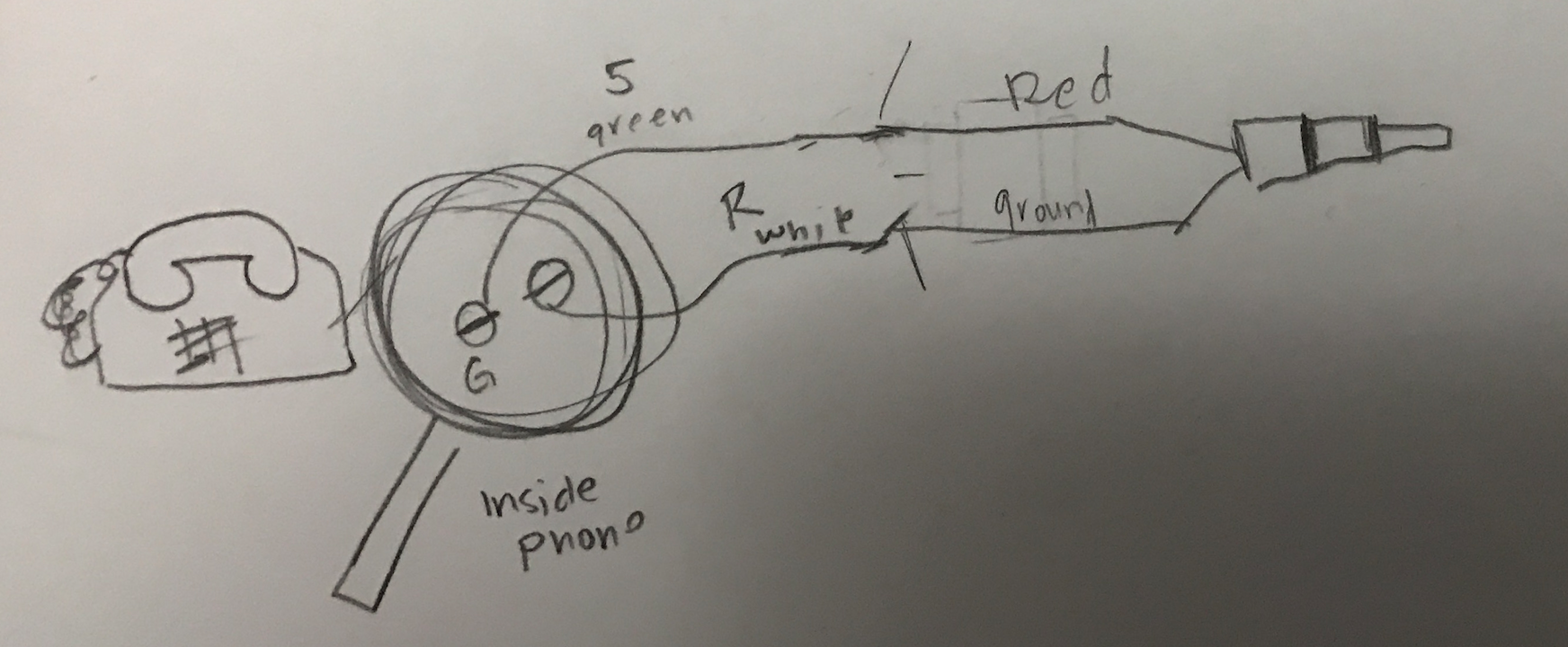
I decided to abandon the cord from the back of the phone and connect directly to the wires and locations in the phone’s original console that came directly from the speaker in the headset. 5 & R were the direct connection spots.

This worked great for sound. It was loud, clear. And it didn’t require extra components. I used my own wires and pulled them out through the hole in the back of the phone made for the original wall cord.
(In retrospect, this would have worked if the wall cord had four wires in it, not just the two. If I had a different cord I would not have had to go through all of these extra steps.)
Pulling the wires directly from the interior of the phone set up meant that it was no longer connected to the phone hook/receiver that cuts off the sound when the phone gets hung up. In this set up, when the phone is placed on the hook, the audio does not completely disappear from playing in the headset, it just gets played at a lower volume.
I needed to create a switch between the receiver, speaker connection.
I tested the different connections on the phone console to see which wire within the console was connected to both the speaker circuit and the on/off receiver of the phone. I found that the left side of the LI connection connected to the lever switch. When I removed the original ground wire and replaced it with connection point at LI, I had the same results as when the phone was connected through the phone wall jack in the back. This was not good.
So I decided to use the wires directly connected to the lever within the phone console. Red and white on the left was one side of the switch, blue and red on the right were the other. I found the origin locations within the main console of the phone, which was a stronger place to, as soldering in this location was unstable.

Now the headset was read to go. When picked up from the receiver sound was audible. When placed back on the receiver the audio would go silent.
Coding the Phone
Last week I was able to set up a program where a 7 digit phone number input would send a serial value if it matched a number pre-programmed in the phone. If the number did not match, then the console would log that it had failed.
When interfacing the aruduino serial values in Isadora, I still need to figure out a way to serial write each keypad input. As of now I have a serial value sending out ONLY when the correct 7 digit number is dialed. When interfacing with the ARDUINO IDE, the println functions allow me to see what numbers have been pressed. However, bringing that same code into Isadora, I can only see the final serial value programmed to trigger something in Isadora. It does not print all of the input values in Isadora – from what I have set up at this point. This means that it is impossible to know where in the array of 7 input digits the user is, and whether or not the numbers are going through. If I think I dialed 7 correct numbers and nothing happens in isadora, there is no way for me to verify that. And there is no way to know when the 7 digit array starts over again.
In order to fix this issue, I went back to the arduino side, to code an array reset if the phone is placed back on the hook.
First I needed to pull in the receiver lines to the arduino and set this up as a HIGH/LOW if statement. 
Initially I was getting 01010101 results back and forth for an LOW position. I changed the pinMode to INPUT_PULLUP and it worked perfectly. The set up of the original phone was a pull up.
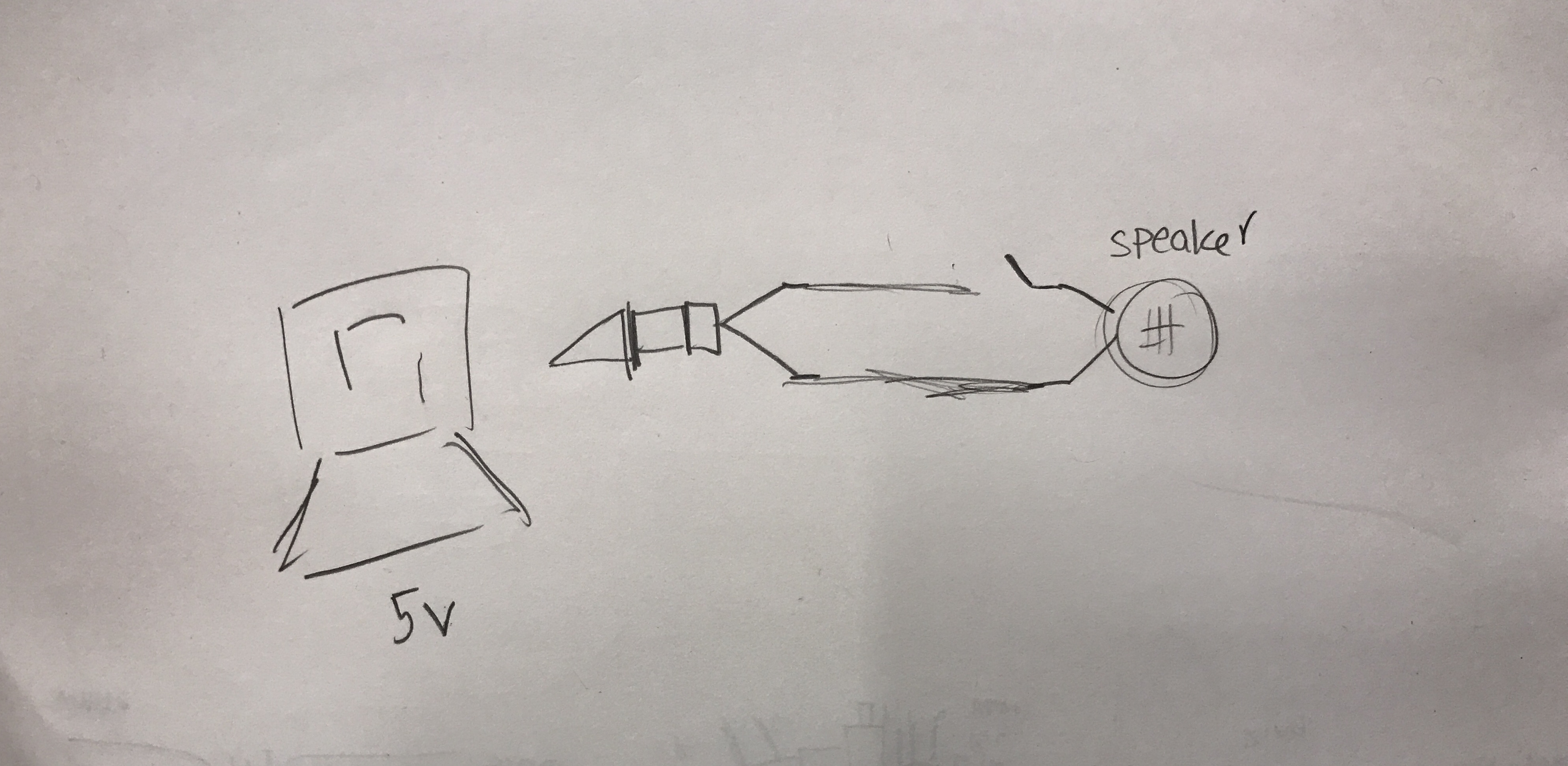
Since the speakers were getting 5 volts from the computer, they were powered fine. Adding the 5v from the computer via the arduino cord powered up the arduino. I am unsure if the circuit is getting double voltage by having two ends connected to the computer. I didn’t have too many issues except for a few times the USB port shut down for too much power. This is something to look into.
I needed to code the program so that when the phone is hung up, it resets the array, so when it is picked up from the reciever again, the user can input a fresh, new series of numbers.
Step 4: Putting It All Together
It did not end here. I showed the phone to Aaron Parsekian and the first thing he did was take the wire cutters and removed the unnecessary pieces of the phone that I was afraid to take out, leaving only the necessary wires available. Thus uncovering several options for switches connected to the receiver.


At a certain point the board shut down and I had to take apart the circuit before it could be used again. The issue seemed to stem possibly from the button switch being made from the phone. I talked with Tom Igoe who reassured me that the board was in fact not dead, as I had originally thought. I spoke with Danny Rozin who suggested getting the highest resister possible in the circuit between switch and the board. This did the trick.

Rough drawing of the circuit. Higher resistor added and changed to around 35-45K ohms.
Fitting the keypad back into the architecture was a challenge. At first it was a bit too snug, causing the receiver not to work when the phone was on the hook. It would continue to act as a closed switch and never fully push down hard enough on the hook to open the circuit. So I cut all of the wires and re-soldered the lines extending from the keypad to the board, creating a flatter device to fit into the body of the phone. This worked. And finally all parts were working kindly in the arduino IDE.

Step 5: Serial Communication with Isadora & Max
Earlier this semester I had experimented with serial communication from Arduino into Isadora. Using that patch I tested out some of the values from Arduino. I was getting strange results in Isadora and realized that perhaps my translation of how it works was incorrect. So I referred back to this tutorial and changed up the code. The serial input data came in accurately and a lot clearer, however there was some sort of delay or discrepancy happening. This part of the process needs a lot more work, and in the end I may switch over to Max MSP for the final interaction.
To be continued…
Leave a Reply