
DESIGN CHALLENGE: Redo one of the previous projects – make it better
Vintangible Radio from Angela at ITP on Vimeo.
I decided to combine the previous design challenges of music controller and lighting controller into one device – a radio 12 channels and with a sliding pot controlling songs within each channel, where lights clearly indicating exactly which channel the user is on.
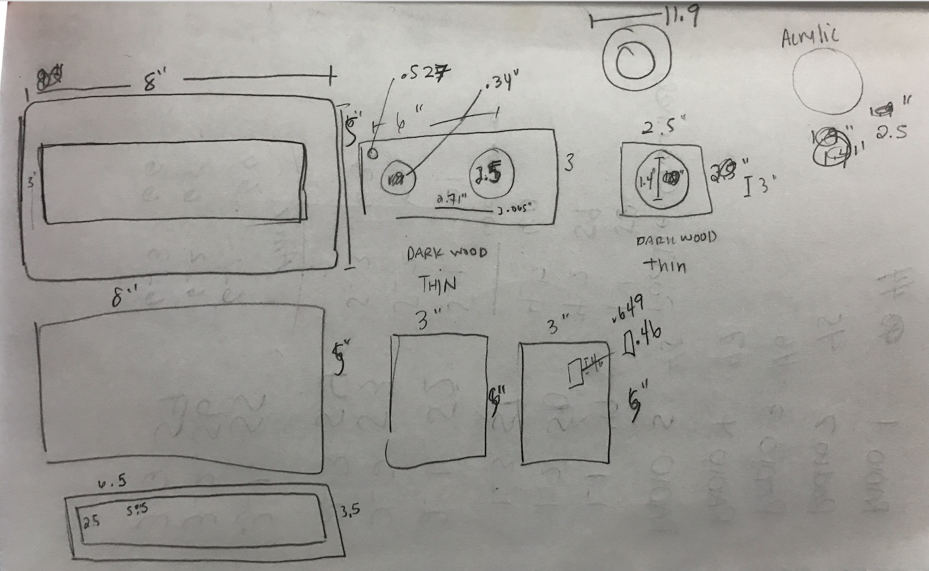
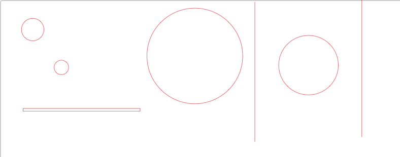
For this piece I began with a strong design plan in mind, which informed how I would bring the rest of the pieces together. So I will start with the design plan.
Design Plan
One idea was to have this be an all inclusive, autonomous device where the music would pull from the SD card on the microcontroller and play out of a speaker within its own circuit. However, as documented, the project evolved to have a similar look to the original plan, but stayed connected to the computer for serial communication, controlling a radio program in p5.js. 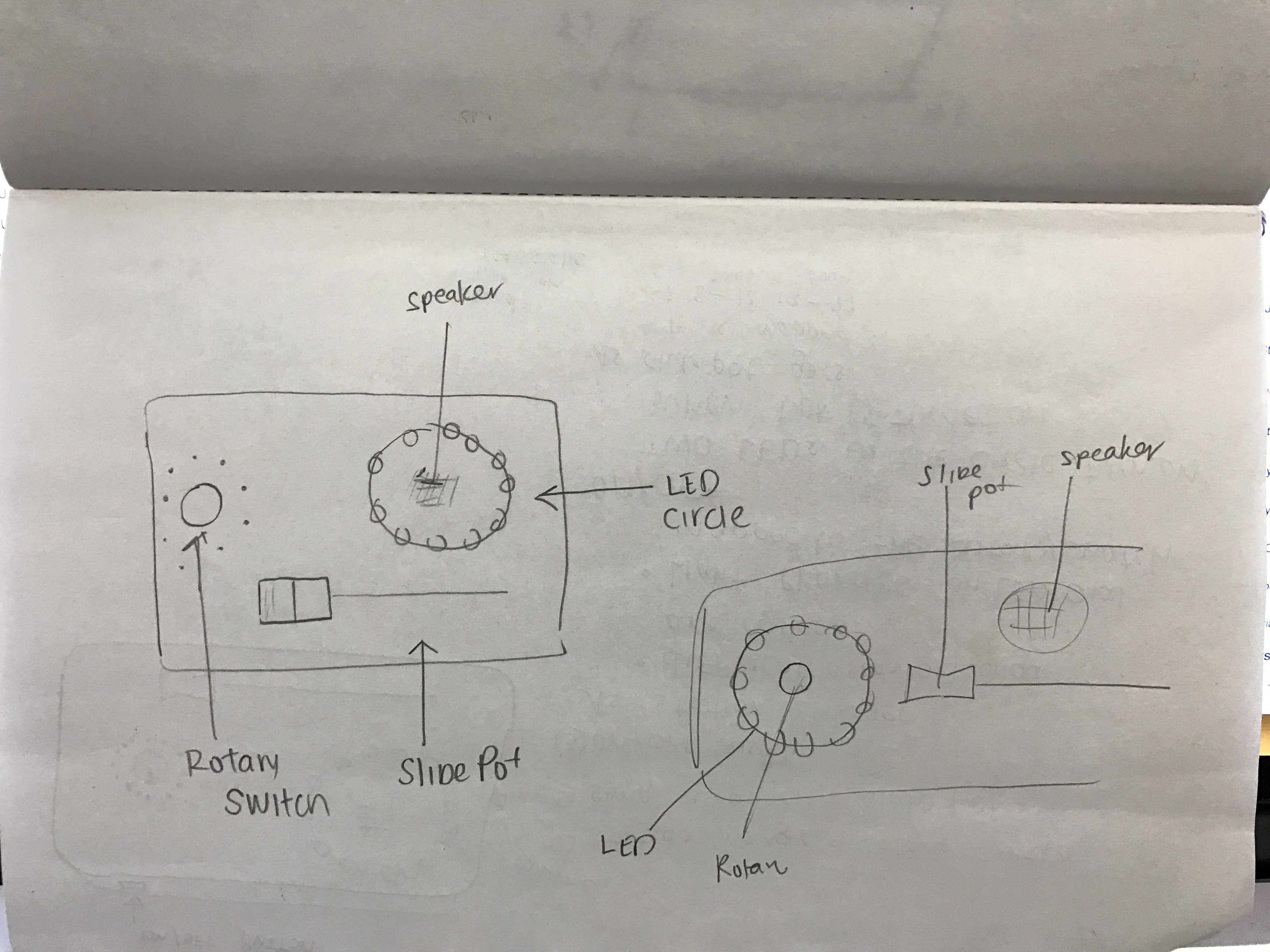
The Process
STEP ONE: Setting Up the Rotary Switch
For the main radio channel control, I used the 1 Pole 12 Position Rotary Switch from Parts Express (Here is the data sheet).
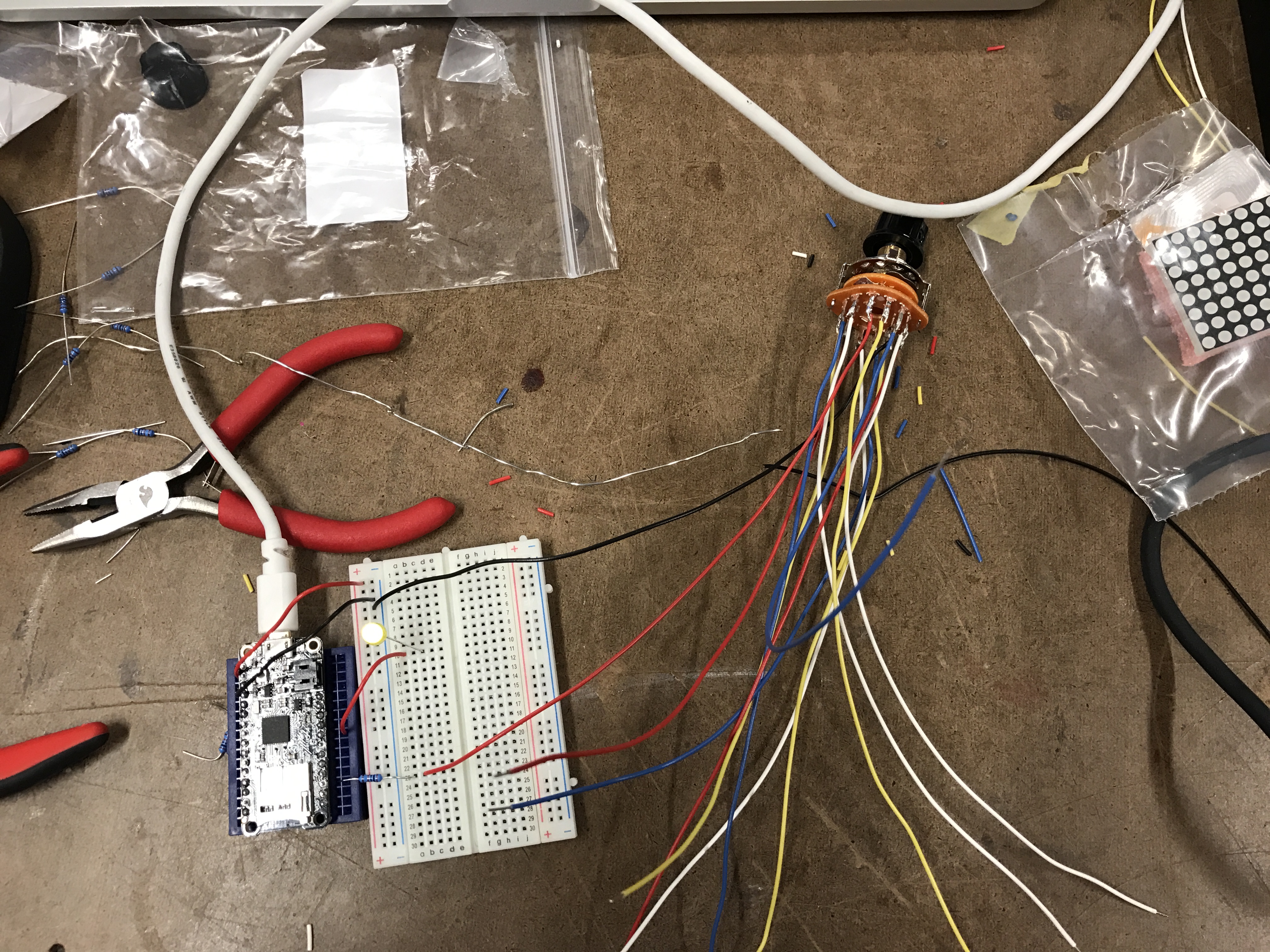
I wired up the rotary switch where a wire came from each pin on the switch.

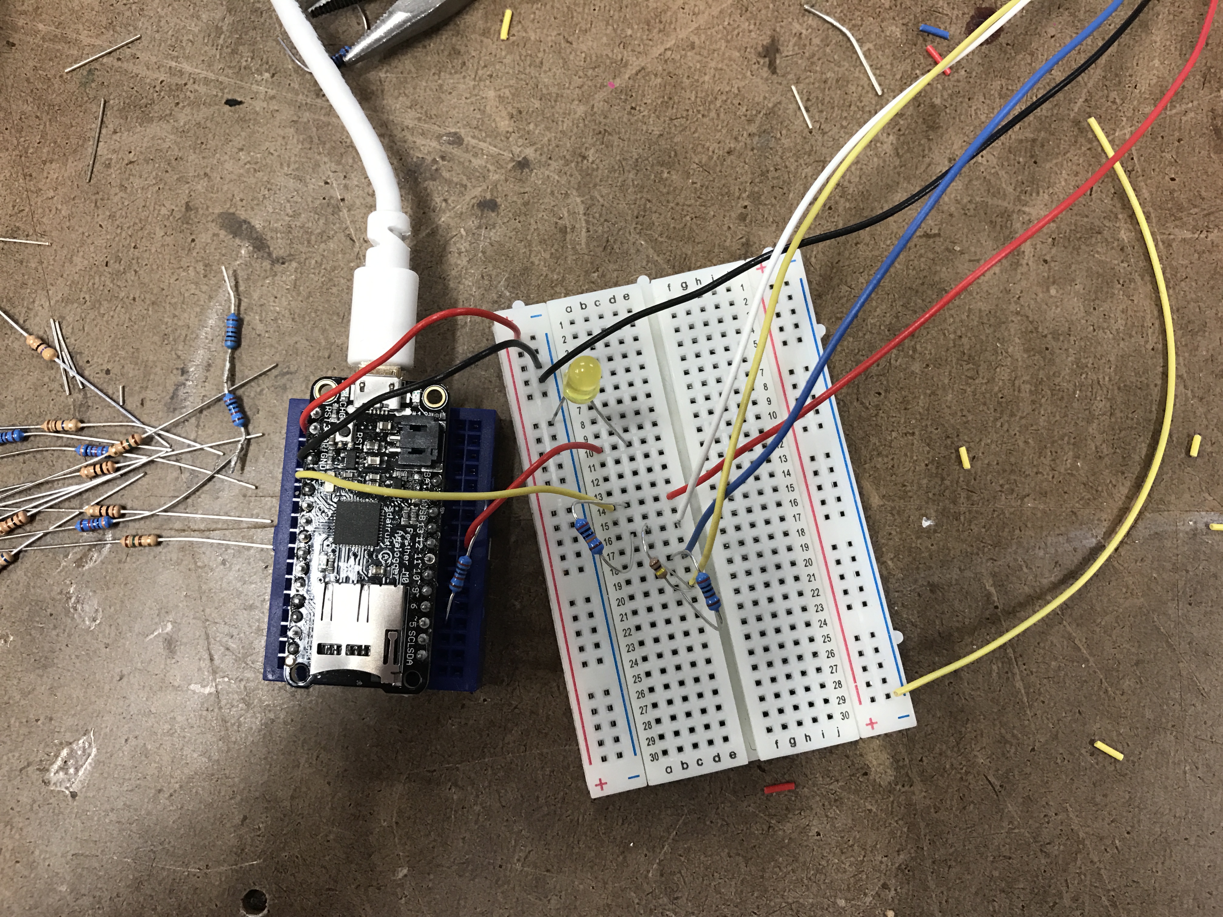
I tested out one basic connection to light one LED based on one position, and it worked!
Resistor Ladder
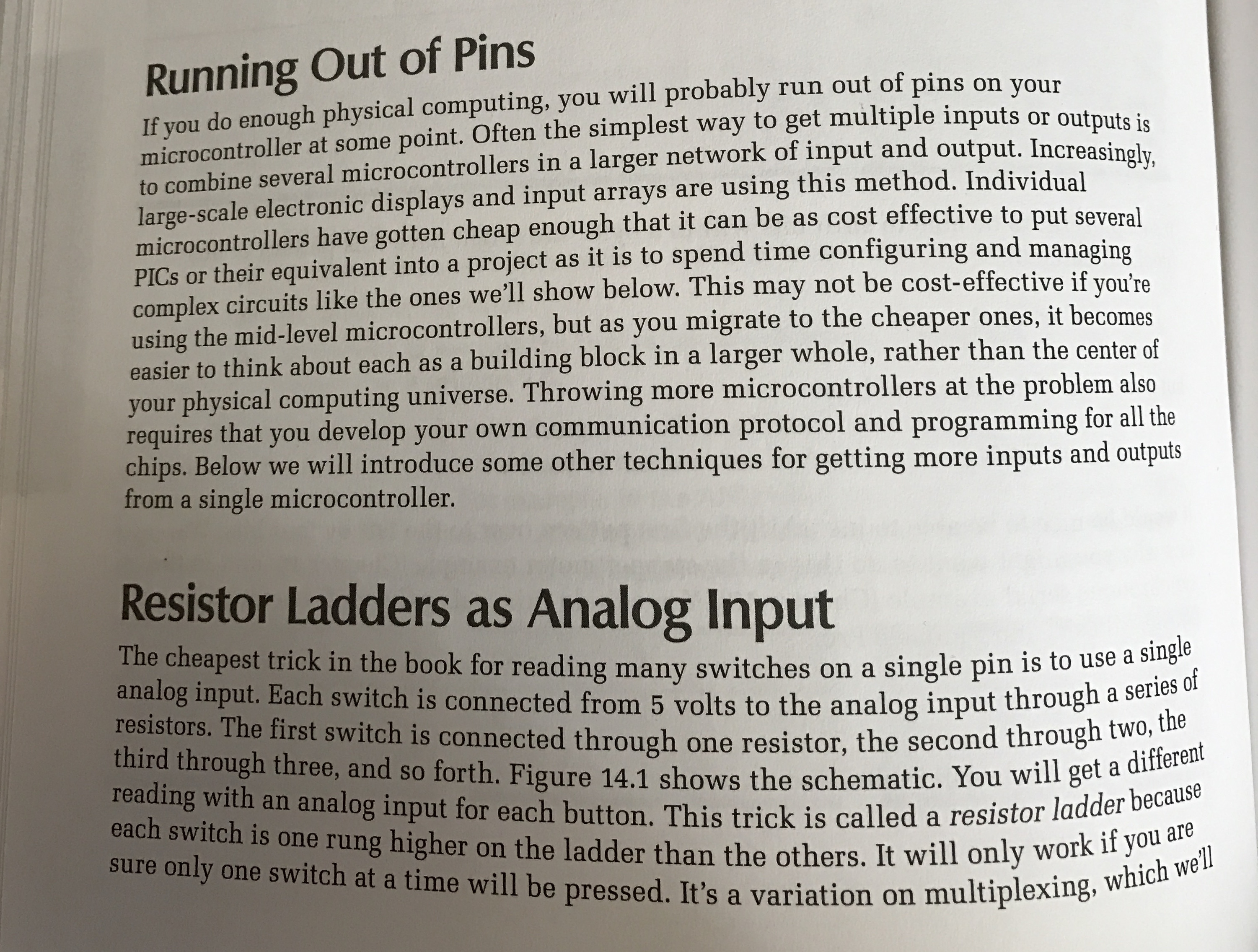
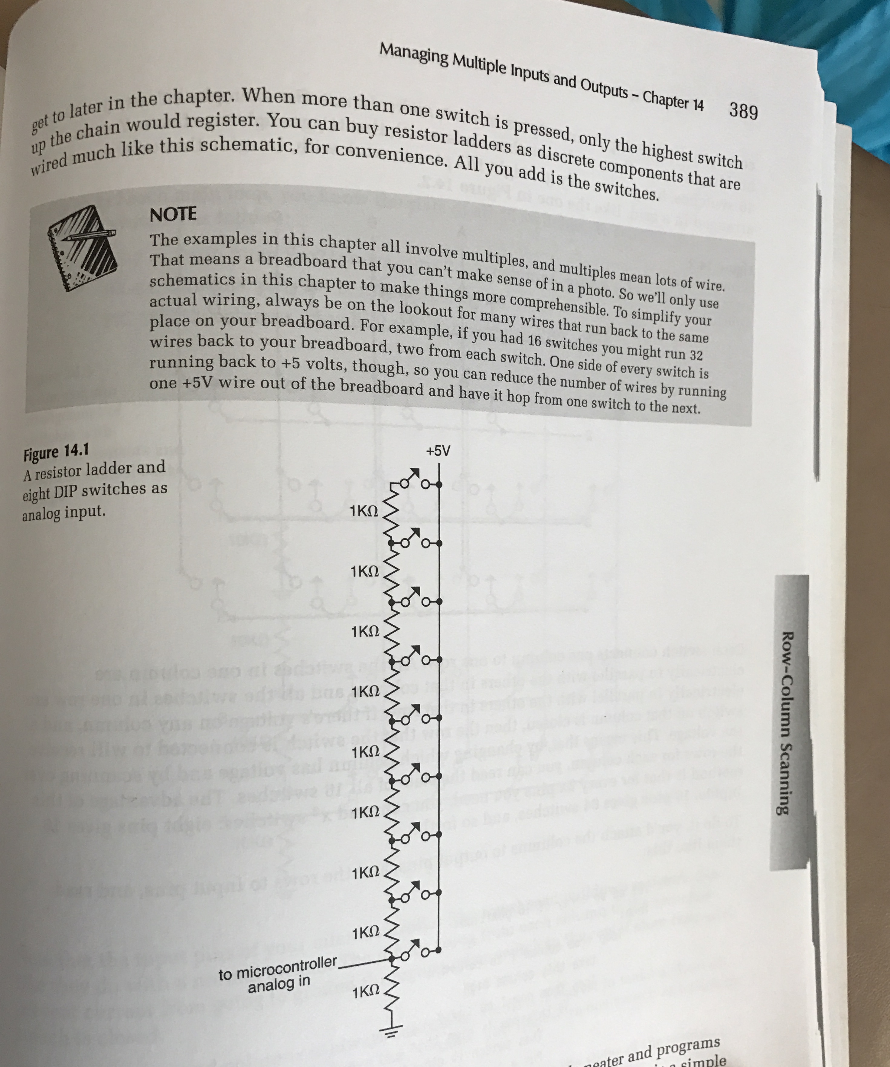
Since there are 12 pins on the switch and not enough to match on the microcontroller, I decided to test out my luck with a resistor ladder – where I would be able to get 12 values from one pin – with each of the 12 switches being connected to one more resistor than the one previous, providing 12 distinct readings from one output pin.
“Physical Computing: Sensing and Controlling the Physical World with Computers” by Dan O’Sullivan & Tom Igoe
“Physical Computing: Sensing and Controlling the Physical World with Computers” by Dan O’Sullivan & Tom Igoe
I looked at this book(see below) & this site for schematic reference to making an resistor ladder.
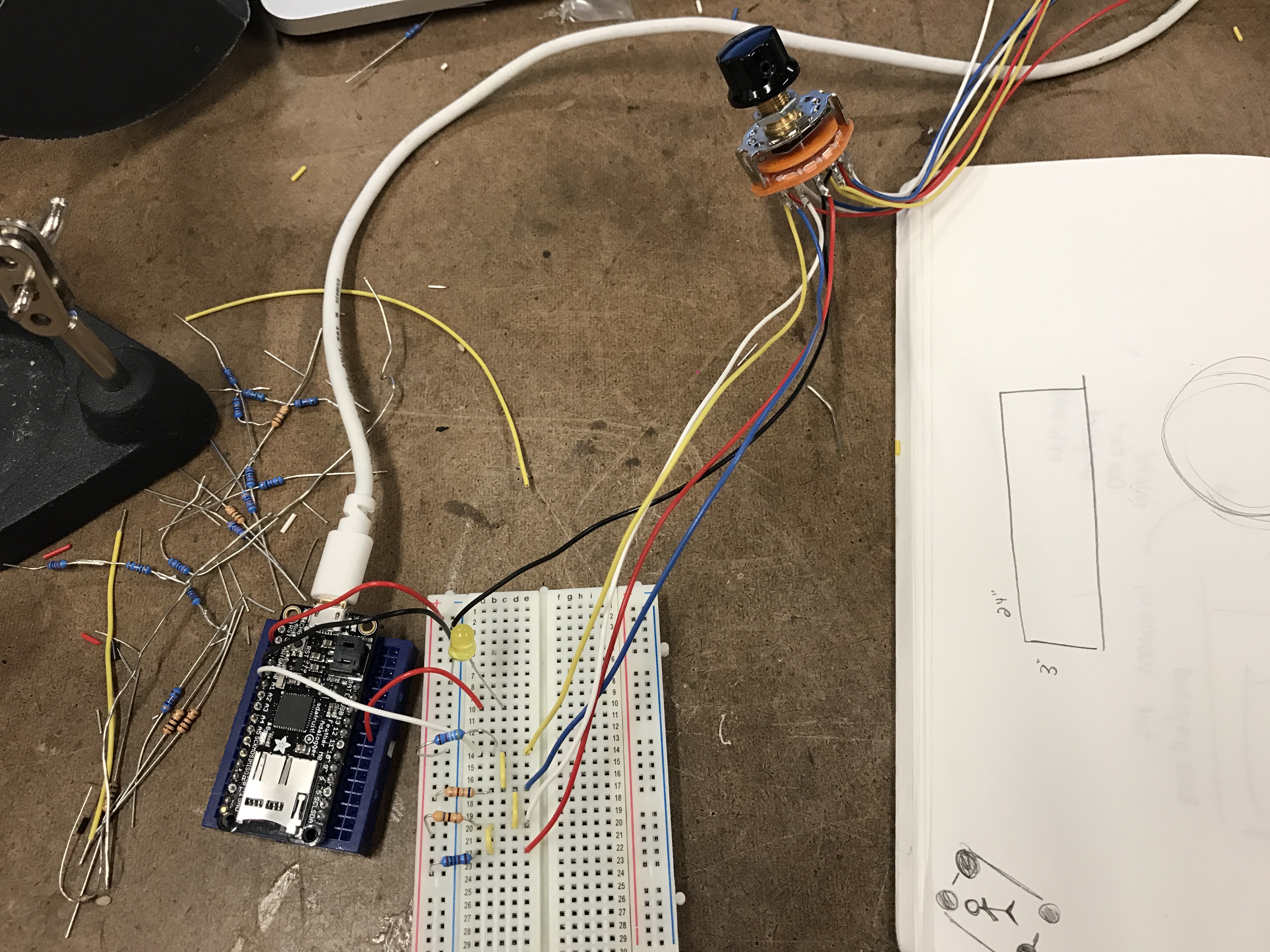
- At first I tried to create a resistor ladder from the base of the long wires, but had trouble getting the wires to line up correctly and it was a bit of a mess. I had added multiple resistors to the ends of the wires coming from each pin on the rotary switch- 20k ohm resistors – 1 on the first, 2 on the second 3 etc. Very sloppy results
- I then added resistors of different levels between the wires – This was still sloppy and did not work.
- I tried INPUT_PULLUP and just INPUT. But the connection was very unstable.
- Based on that diagram I tried using the last pinout to go to negative instead of the positive branch but that didn’t make sense since the rotary switch’s negative out is already connected.
This is one way I could have done it, but I already soldered the wires. Basically I octopused it, when I should have resistor-laddered it from the original pin points on the rotary switch.
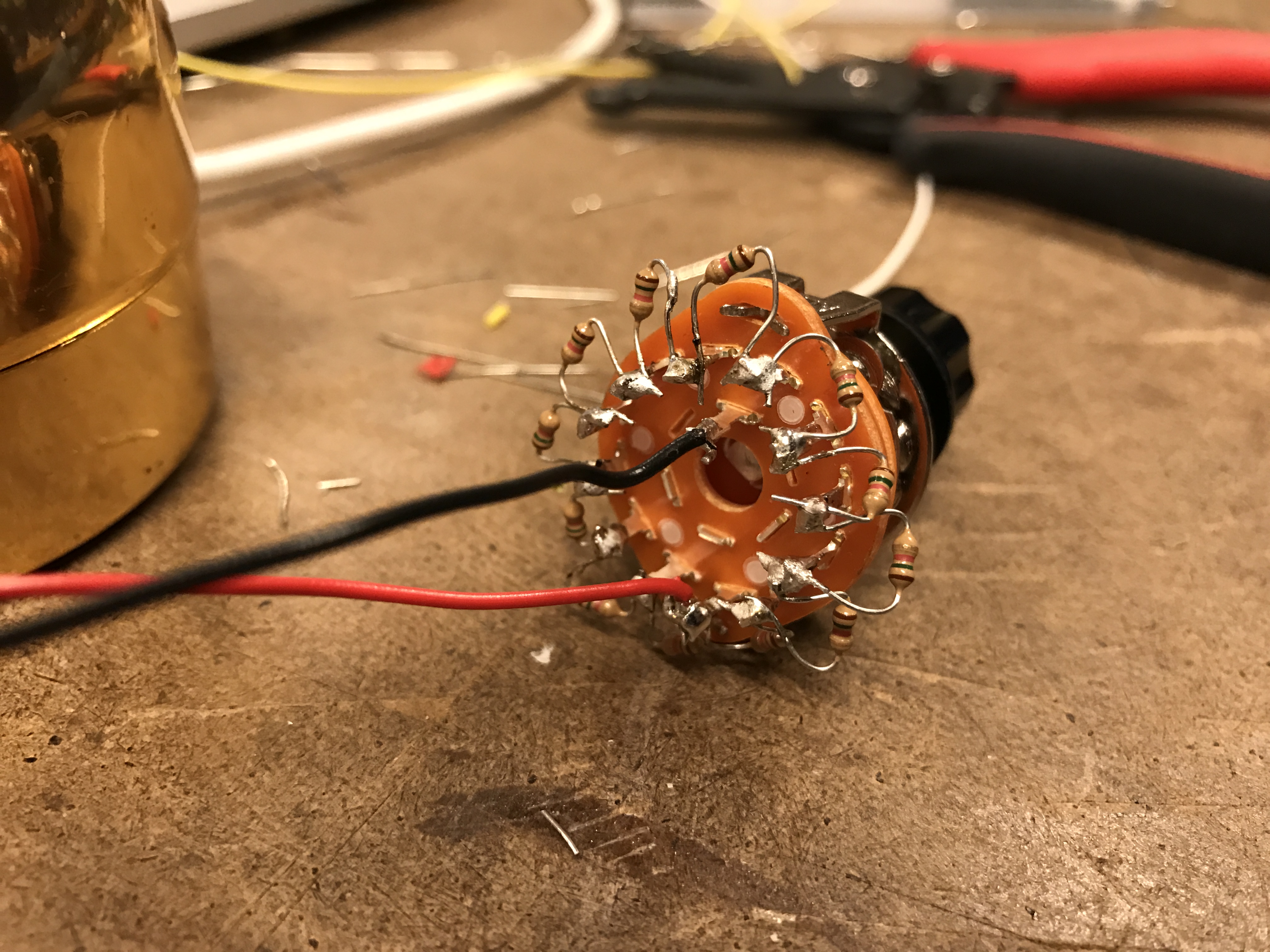
So, I did just that. I desoldered the wires and did the simplified formation of the resistor ladder:
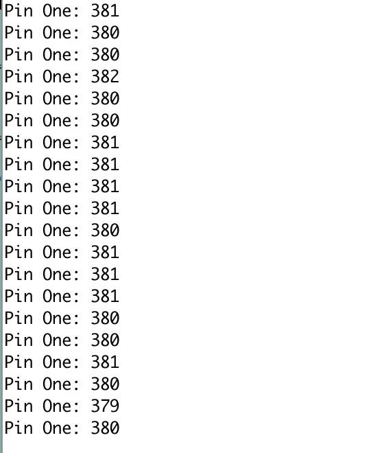
At first, the connection did not work. I kept getting the same values of 6 or 7 in the analogRead. I tried it both as INPUT and INPUT_PULLUP and both yielded the same results.
I noticed that in any online image, the rotary pin that also connected to the Analog input did not connect to the rotary pin next to it. It was also the end of the circuit. (see again here). I had built mine so that the resistors looped around fully and that each rotary pin connected to the one next to it, with no break or space. This did not work, again in either INPUT or INPUT_PULLUP.
Then I realized…I DIDN’T HAVE A PIN GOING INTO POWER, just going into an analog pin. However with the power pin going and analog pin both going out from the rotary pin, it did not work. The result was 1023 for every change. Then I switched to the analog to come from the negative side and that yielded again the 7,6,7,6 output.
I checked into this set-up which added a third line to the rotary switch, with power and ground coming out of either side of the ladder and the third analogRead wire coming out of the center line that was previously used in my circuit as ground.
IT WORKED! Each turn provided a different, semi stable output.

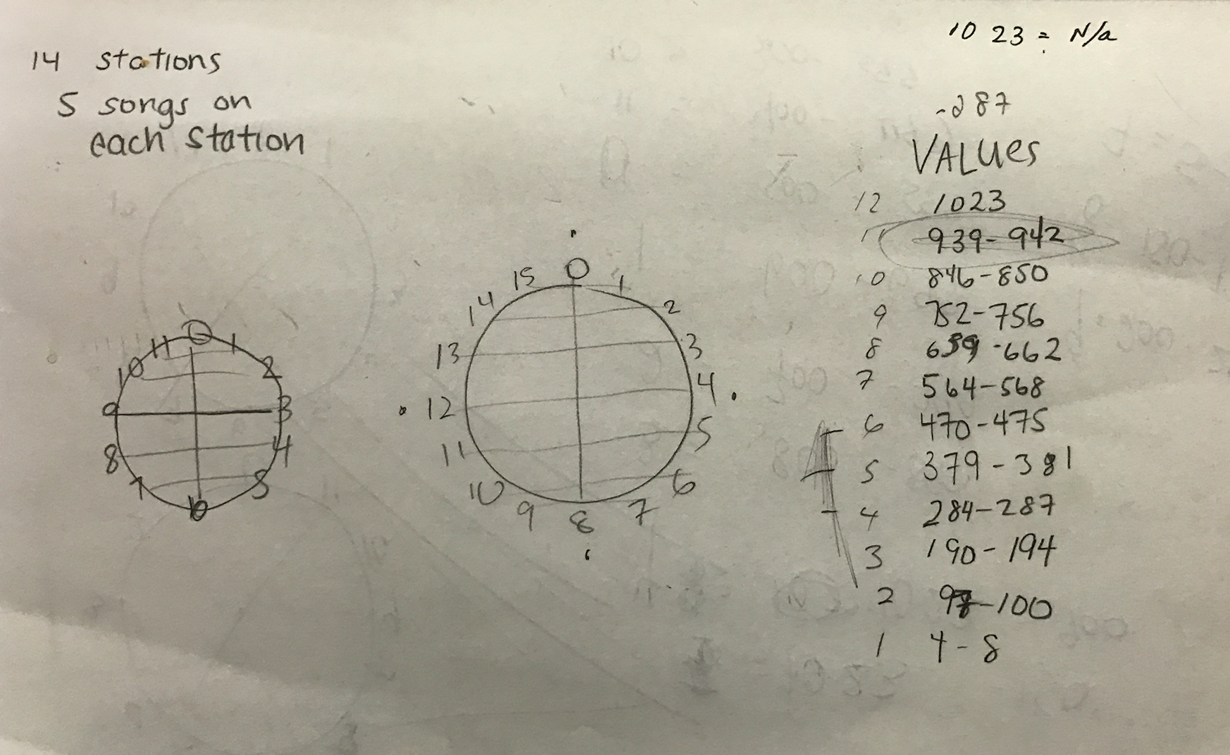
Connecting Values to Switches
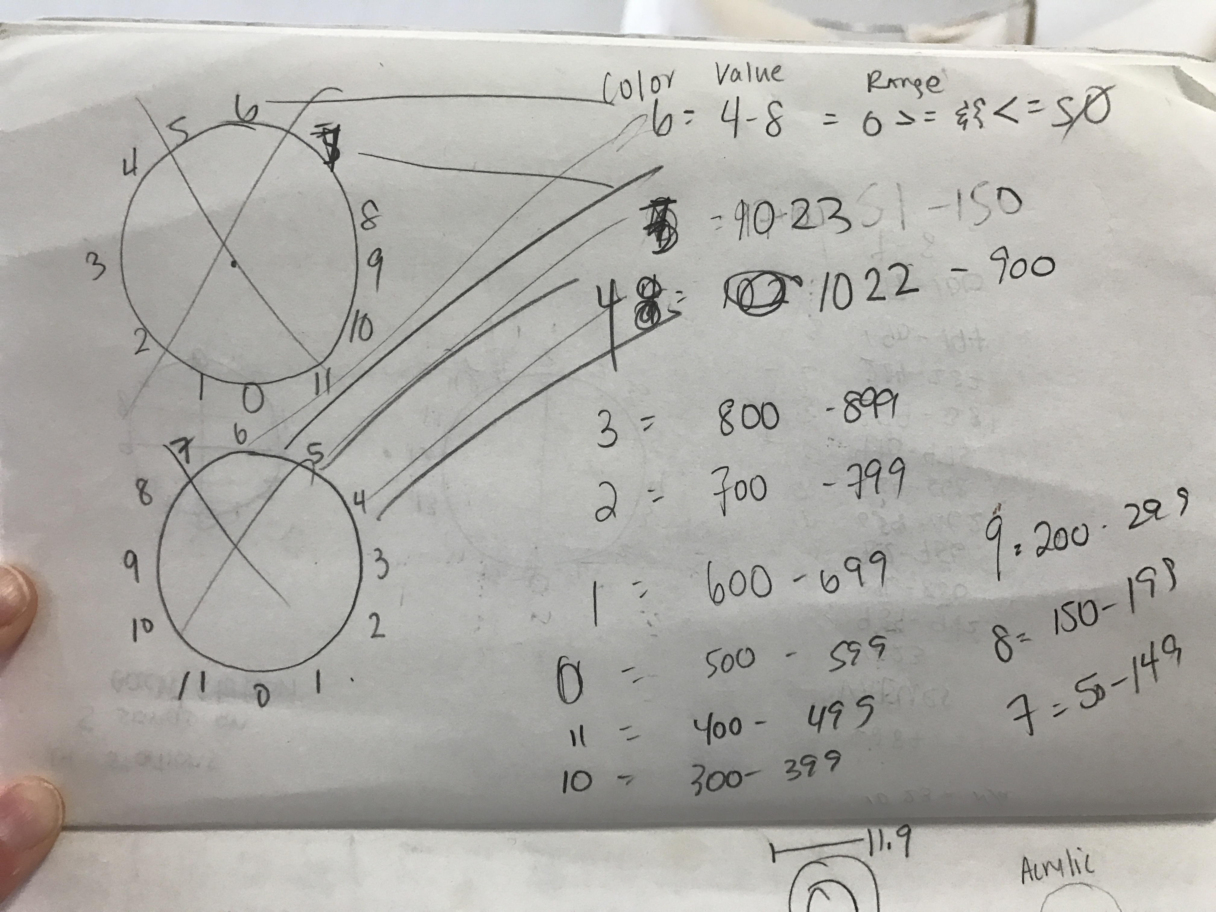
Connecting Values to Switches
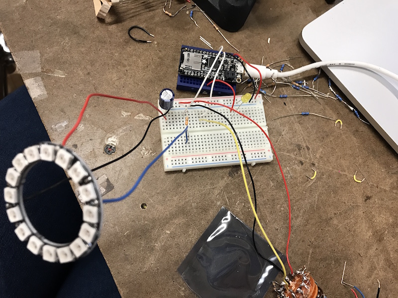
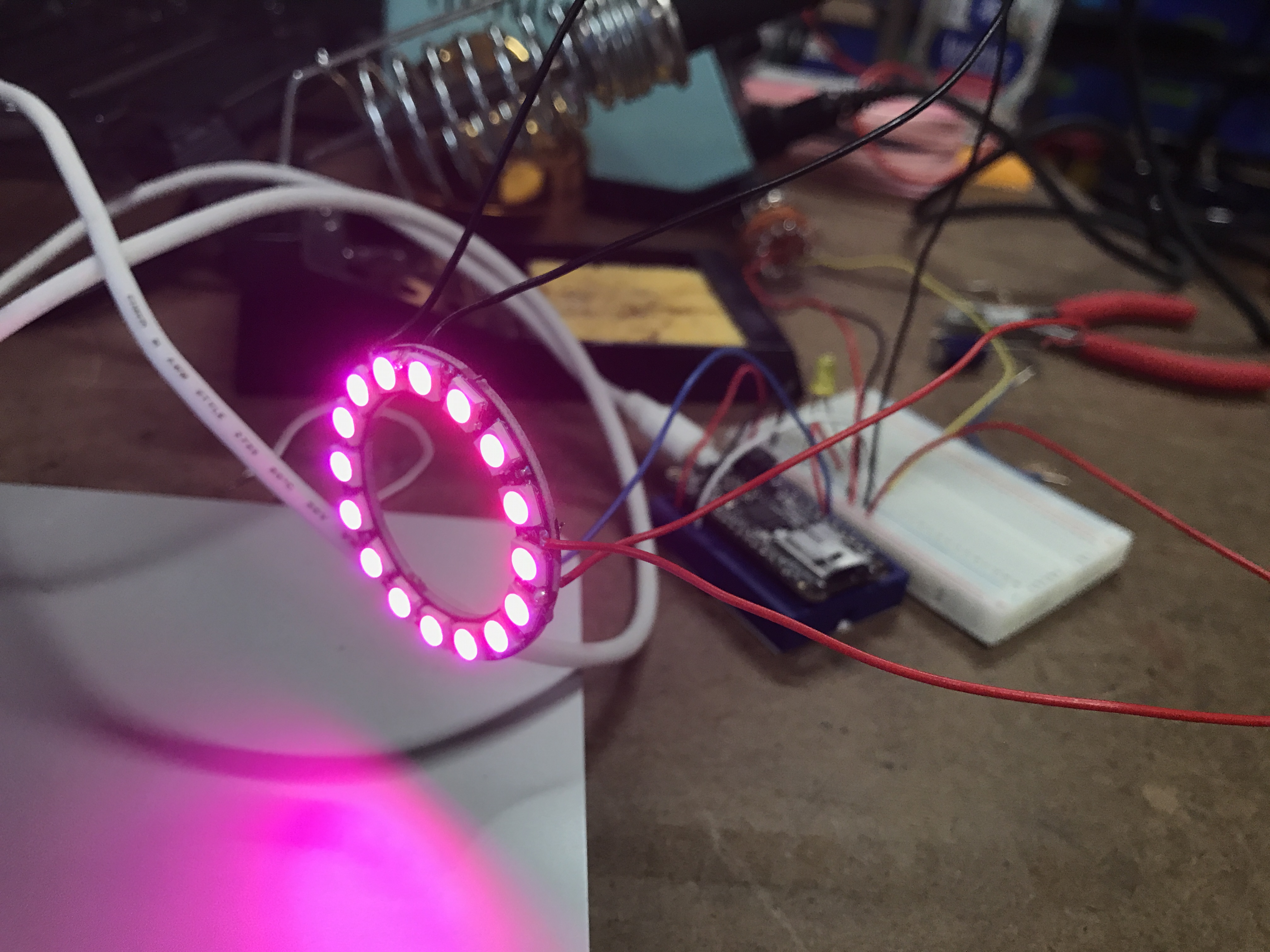
STEP 2: Set Up Neopixel Ring
The neopixel ring that I started with was a 16 LED ring from Tinkersphere. It is by duinospeak, not Adafruit. With the same set-up, I assumed that it would work with the Adafruit code, since there was no tutorial or code available and since the connections and setup mirrored that of Adafruit’s neopixel ring.
The multimeter verified that the soldered connections were good. I tried wiring the ring to the board several ways from basic to adding a capacitor and a resistor as seen this tutorial, but it did not work.
Next I soldered the the second set of positive and ground pins to the ring. I set it up with the capacitor and nothing happened (1000uF, 16v). I removed the cap and got a weird sequence (example simple). I unplugged, tried it again and it did not work at all.
I switched again the pins on the board that it was attached and changed the pin input pin and then it worked. That was a fun 2 hours. I didn’t even need a resistor or capacitor. Although the colors kept changing every so often. This was with example strandtest. This was the Adafruit tutorial that I used but was not necessarily helpful.
Then I tried programming specific pixels to light.
The first time I uploaded the code the LEDs never changed.
The second time I uploaded it worked for 3/4 of the LEDs programmed.
I moved the spots that power and ground connected to on the board and then it did not work at all.
I added a delay. Didn’t work. I changed the board. Didn’t work. I switched the sides of the board and it didn’t work. I changed the board again. Didn’t work. I borrowed someone’s Adafruit neopixel ring and it worked perfectly differently from how it worked before. Which again, leads me to believe that the board is the issue. I tried it again and it didn’t work. I re-soldered the digital in connection. Still didn’t work.
One of the strange outputs that did not perform what the code examples called for.
I tried a number of other ways to connect this board and it did not work.
I went back to Tinkersphere and exchanged the board. I came back, soldered it up and it still did not work. Instead I switched to a 12 pixel ring and it worked the first time. Same circuit. No changes. (As it turns out, after some troubleshooting with Tinkersphere – they have a great service – the reason for the 16- neopixel ring not working was a voltage issue. The feather m0 only give sout 3v when that neopixel ring, with its abundance of neopixels, required more voltate. This could have worked on an arduino.)
I noticed that if you update the code for the pixels and upload that, somehow the code from before seemed to stay programmed in ring. Turns out this code was missing in the setup:
pixels.show(); //initializes as off
STEP 3: Connect Values from Rotary Switch to the Neopixel Ring
Starting with just one pixel on the ring and one value on the rotary switch, I was able to use the switch state to light the one pixel when it hit that position on the rotary switch. However, it would not go off. I tried various ways in the code to shut it off, playing with brightness and some guessing. I sniffed around the library’s github and did some experimenting. After looking through the buttoncycler example code, I tried this line out and it worked for shutting the pixel off when the rotary switch changed:
pixels.setPixelColor(6, pixels.Color(52,255,107,0));
Adding in the 0 at the end, shut off the pixel. Tried it again, and it didn’t work. It wouldn’t even initialize as off. All I did was go from arduino to the browser to document this and it stopped working. Something seemed wrong with the board. I uploaded a sample sketch and nothing changed on the neopixel ring. So I unplugged, reset the board and re-uploaded the sample sketch.
I looked again at the buttoncycler sample code and adjusted the line of code to shut off the pixel to:
pixels.setPixelColor(6, 0);
I next went pixel by pixel, matching each to a rotary position. Once that was working. Some values seemed to overlap causing a blinking glitch, so I went over each value and redid them to have smoother transitions.
STEP 4: Remove Hot Glue From Card Slot in Mac
At this point I was contemplating using the SD card on the Adalogger m0 board for a song player instead of using a p5 sketch, so the device I am making can stand alone as its own music player. When I went to add things to the SD card, I found some hot glue pieces and dust lodged into my computer’s SD card slot. Using a mini Popsicle stick, I was able to dislodge the obstruction and enter my SD card into the slot once again.
STEP 5: Find A Way to Use the SD Card on the Feather
After many unsuccessful tutorial searches and attempts to make this project autonomous by having the code access files from the microcontroller itself, I decided to put this aside and focus on serial communication with a p5 sketch.
STEP 6: Revert Back to p5
For what I actually want to do it seems like I would need multiple serial outputs from Arduino:
- Serial output #1 controlling rotary switch for the channel – refers to a array of songs
- Serial output #2 controlling slide pot for individual songs from the arrays set by serial output 1
So instead I decided to experiment with code where with the arduino code, if certain conditions are met then it triggers a song from a giant list in p5. For example, if the rotary switch has this value AND the sliding potentiomter has this specific value – DO THIS/Serial.write() THIS…etc, for all of the options. Lots of lines of code, not super efficient, but the job gets done.
Then I jumped back to p5 to play with the code from the music player. I tried the switch statement cases, I tried removing the cases and just doing if Statements, but many times the songs would just get stuck in loops or the page would freeze. Or nothing would work at all.
Finally…after an elongated “experimental period,” I was able to make the code work for all intents and purposes, to do what I wanted it to do. There is definitely a cleaner and more efficient way to write this code, but it is beyond my capabilities at this point.
I had one full channel working with a sliding pot transition of 7 song files.
STEP 7: Adding Multiple Channels
Had issues with getting values from the second position on the rotary with the current code:
//CHANNEL 1 49 - 55
if (rotary >= 0 && rotary <= 49 && slidePot == 0) {
pixels.setPixelColor(6, pixels.Color(52, 255, 107));
pixels.show();
Serial.write(49);
} else if (rotary >= 0 && rotary <= 49 && slidePot == 1) {
pixels.setPixelColor(6, pixels.Color(52, 255, 107));
pixels.show();
Serial.write(50);
} else if (rotary >= 0 && rotary <= 49 && slidePot == 2) {
pixels.setPixelColor(6, pixels.Color(52, 255, 107));
pixels.show();
Serial.write(51);
} else if (rotary >= 0 && rotary <= 49 && slidePot == 3) {
pixels.setPixelColor(6, pixels.Color(52, 255, 107));
pixels.show();
Serial.write(52);
} else if (rotary >= 0 && rotary <= 49 && slidePot == 4) {
pixels.setPixelColor(6, pixels.Color(52, 255, 107));
pixels.show();
Serial.write(53);
} else if (rotary >= 0 && rotary <= 49 && slidePot == 5) {
pixels.setPixelColor(6, pixels.Color(52, 255, 107));
pixels.show();
Serial.write(54);
}else if (rotary >= 0 && rotary <= 49 && slidePot == 6) {
pixels.setPixelColor(6, pixels.Color(52, 255, 107));
pixels.show();
Serial.write(55);
}
else {
pixels.setPixelColor(6, 0);
pixels.show();
}
//CHANNEL 2 56 - 62
if (rotary == 1023 && slidePot == 0) {
pixels.setPixelColor(5, pixels.Color(52, 255, 107));
pixels.show();
Serial.write(56);
} else if (rotary == 1023 && slidePot == 1) {
pixels.setPixelColor(5, pixels.Color(52, 255, 107));
pixels.show();
Serial.write(57);
} else if (rotary == 1023 && slidePot == 2) {
pixels.setPixelColor(5, pixels.Color(52, 255, 107));
pixels.show();
Serial.write(58);
} else if (rotary == 1023 && slidePot == 3) {
pixels.setPixelColor(5, pixels.Color(52, 255, 107));
pixels.show();
Serial.write(59);
} else if (rotary == 1023 && slidePot == 4) {
pixels.setPixelColor(5, pixels.Color(52, 255, 107));
pixels.show();
Serial.write(60);
} else if (rotary == 1023 && slidePot == 5) {
pixels.setPixelColor(5, pixels.Color(52, 255, 107));
pixels.show();
Serial.write(61);
} else if (rotary == 1023 && slidePot == 6) {
pixels.setPixelColor(5, pixels.Color(52, 255, 107));
pixels.show();
Serial.write(62);
} else {
pixels.setPixelColor(5, 0);
pixels.show();
}
It turns out, to get both working to show change in values on the serial monitor, I needed to remove the switch state and it worked!
I took a break to fabricate & solder (more below).
Once the components were soldered up and set in the box, I cleaned up the code so that there were less preloads and lines of code, reusing the radio static instead of creating a new instance of the static per channel.
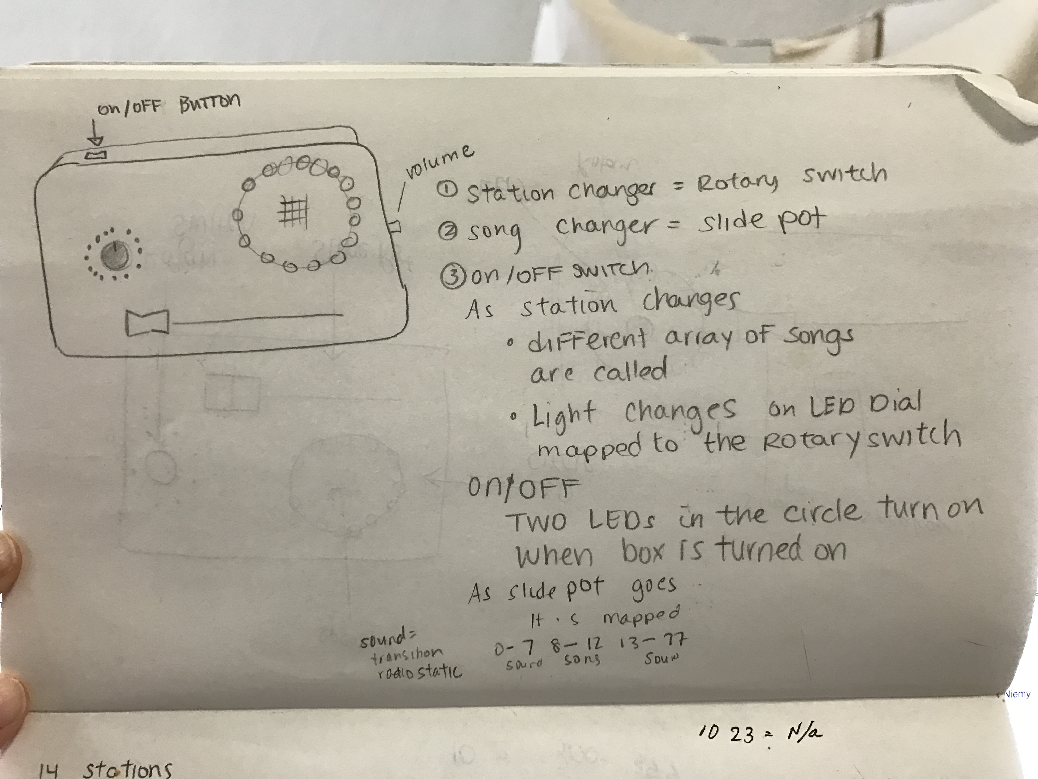
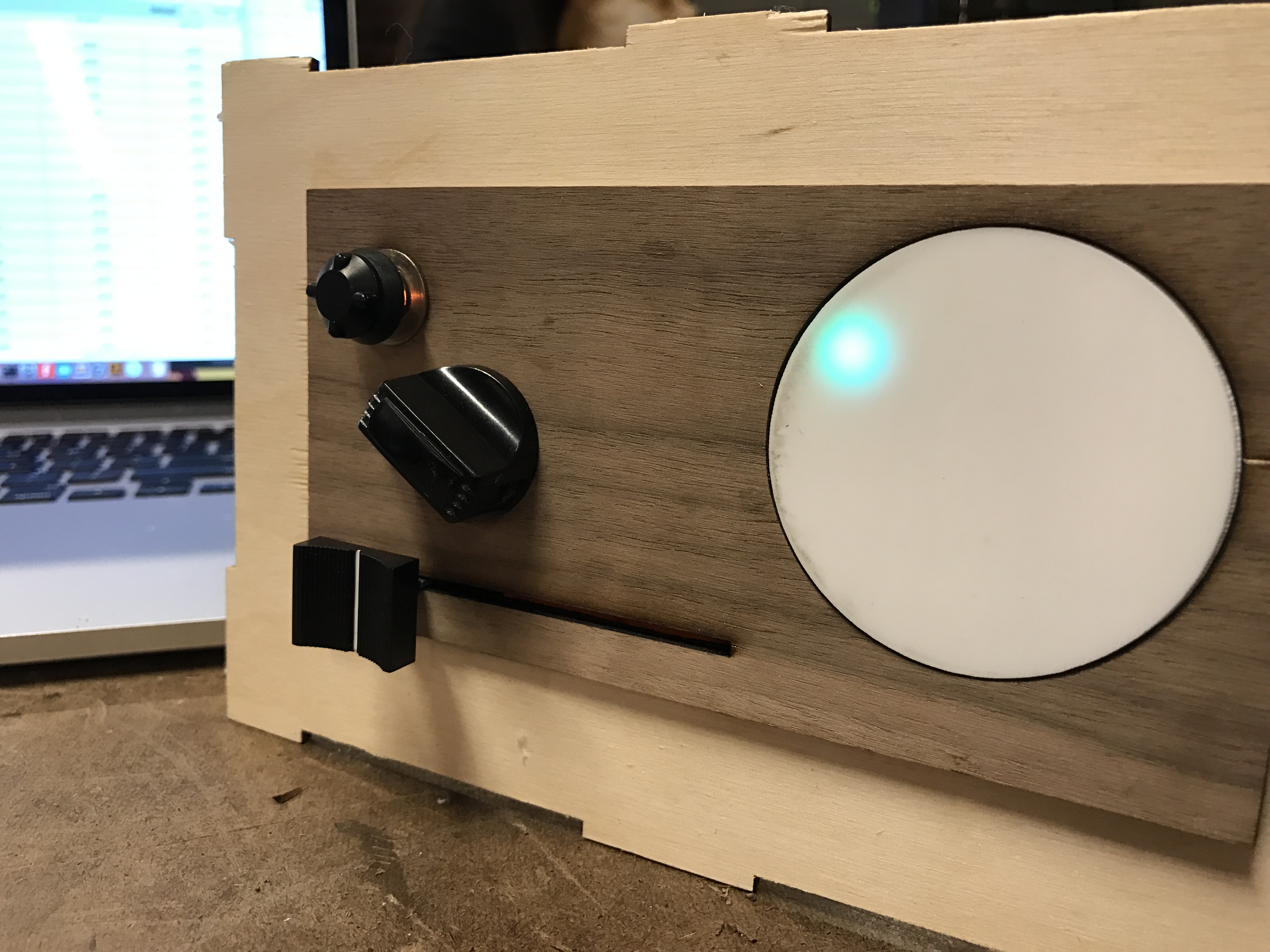
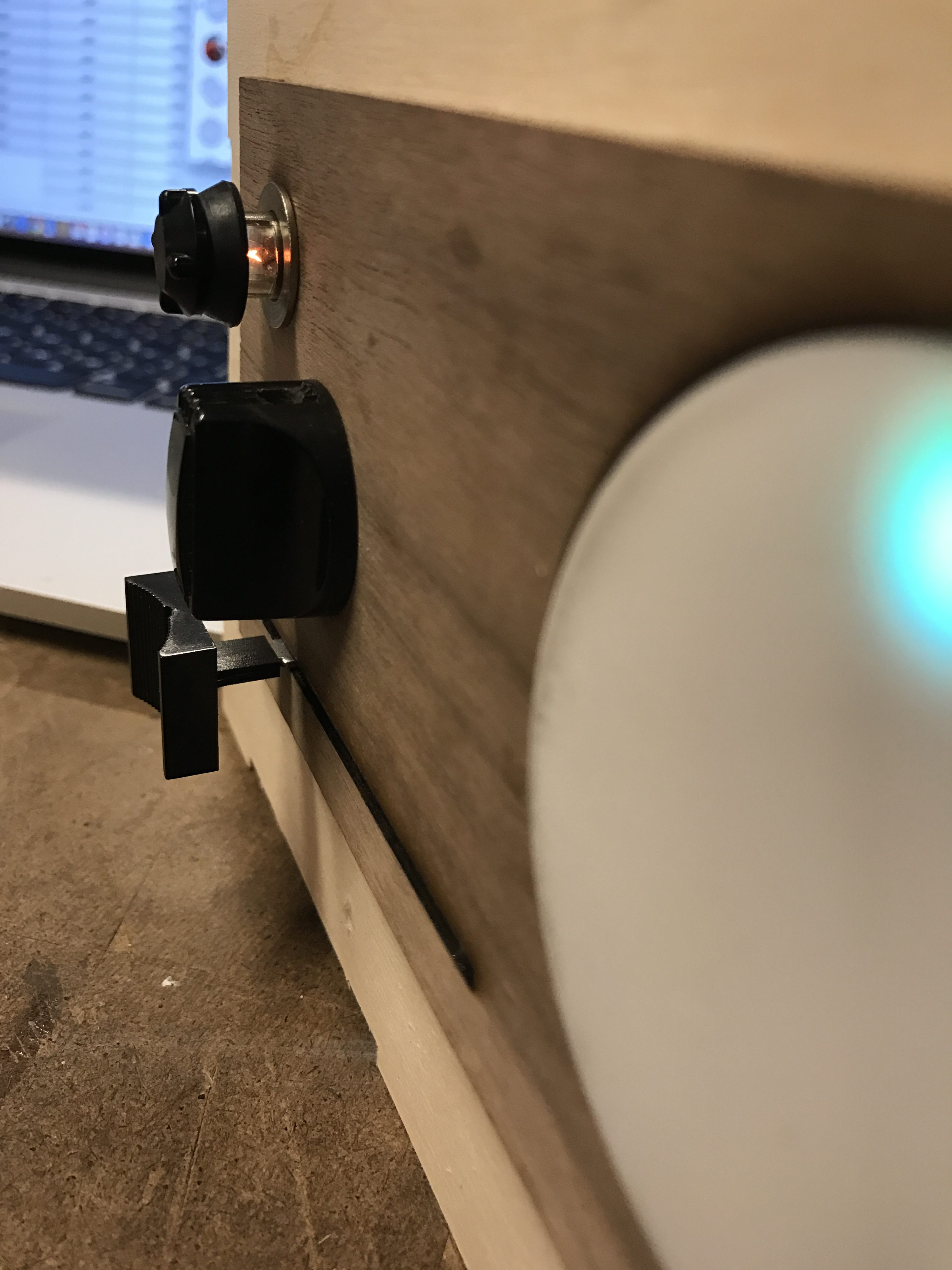
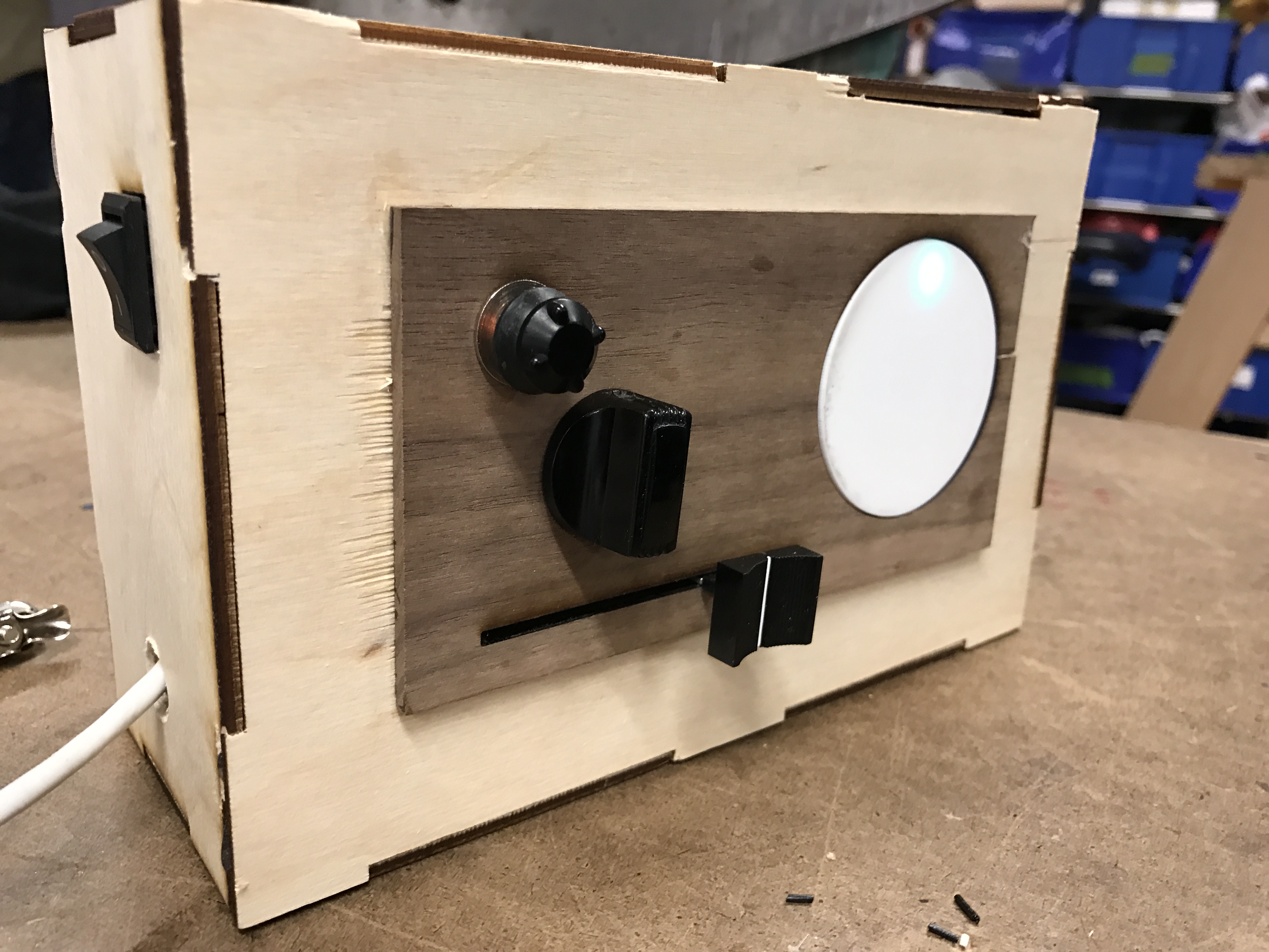
In the end, I created 12 channels, each channel with featuring a different theme of 3 songs PLUS radio static in between. The rotary switch controlled the transition between channels, and the sliding potentiometer controlled the changes between the songs within each channel. A switch on the side of the box turns the radio box on, and a dim light on the top left of the interface shows that the box has been switched on. All of these parts come together to give the box a face, giving the interface a likable and vintagey style persona.


Channel 1 – Sakamoto Kyu Station
Channel 2 – 渋いステーション
Channel 3 – Poodle Station
Channel 4 – Sakamoto Kyu Station Plus
Channel 5 – Cole Porter Station
Channel 6 – Amy Winehouse Station
Channel 7 – TV Themes Station
Channel 8 – Hedwig Station
Channel 9 – Cali Station
Channel 10 – Michael Jackson Station
Channel 11 – 90s Music Station
Channel 12 – Oldies Station
Code
This project required serial communication between the Arduino IDE and p5.js. (Details on setting up serial communication with p5.js can be found here.)
Arduino IDE Code
p5.js Code
Schematics


Fabrication


Other References
Radio_Static.mp3 – http://soundbible.com/2099-AM-Radio-Tuning.html
Fritzing.org
Leave a Reply